Engineering Excellence
From Theory to Flight
A deep dive into the engineering behind our competition aircraft from structural design to computational fluid dynamics.
Structural Design
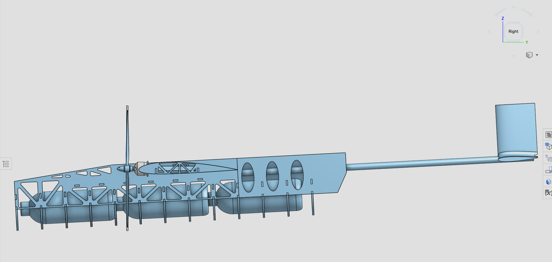
Full Aircraft Assembly
Our fuselage CAD model represents months of meticulous engineering. The design features strategically placed payload bays with weight-saving cutouts, a streamlined tail boom, and a precisely angled vertical stabilizer, all optimized for maximum payload capacity while maintaining structural integrity.
Every truss member, lightening hole, and fastener point has been carefully positioned using finite element analysis to ensure the airframe can withstand competition flight loads while keeping empty weight to an absolute minimum.
Wing Engineering
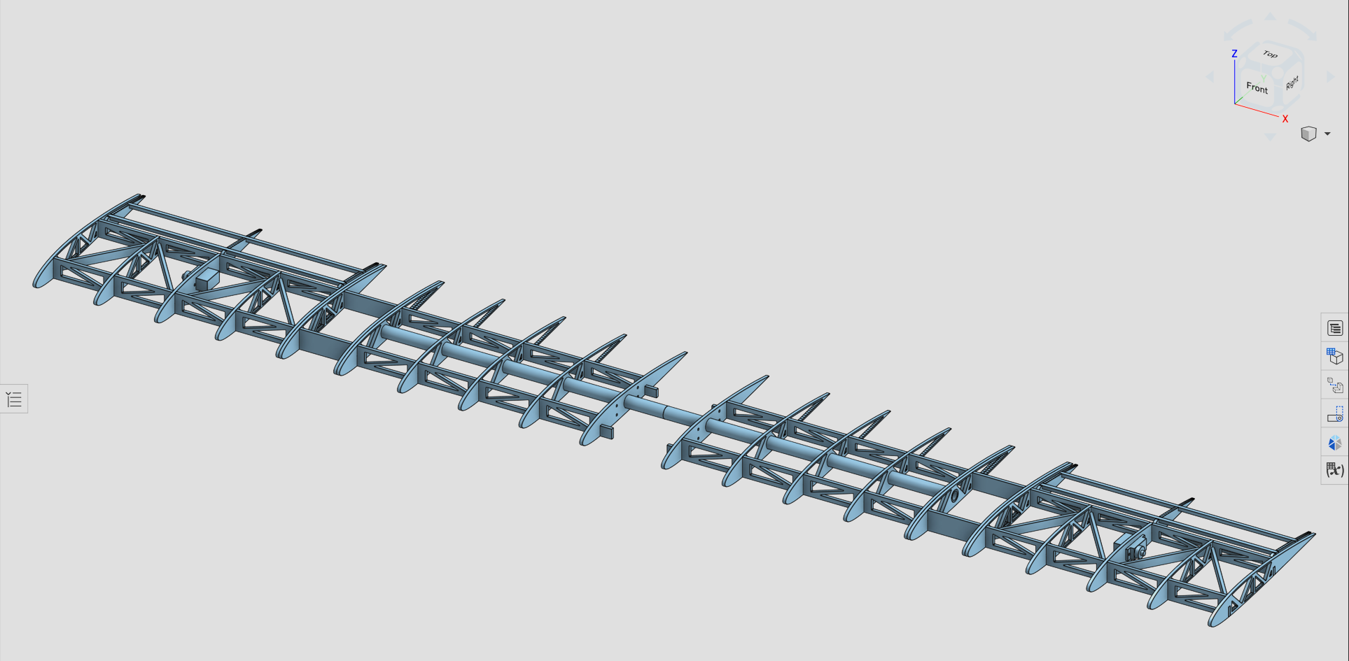
Wing Structural Framework
The backbone of our aircraft is carefully engineered wing structure featuring multiple rib stations connected by dual spars and diagonal truss members. This skeletal framework is designed to distribute aerodynamic loads efficiently across the entire wingspan.
Each rib profile follows the selected airfoil geometry, while the truss configuration provides exceptional torsional stiffness. The modular design allows for easy assembly and repair in competition conditions.
Computational Fluid Dynamics
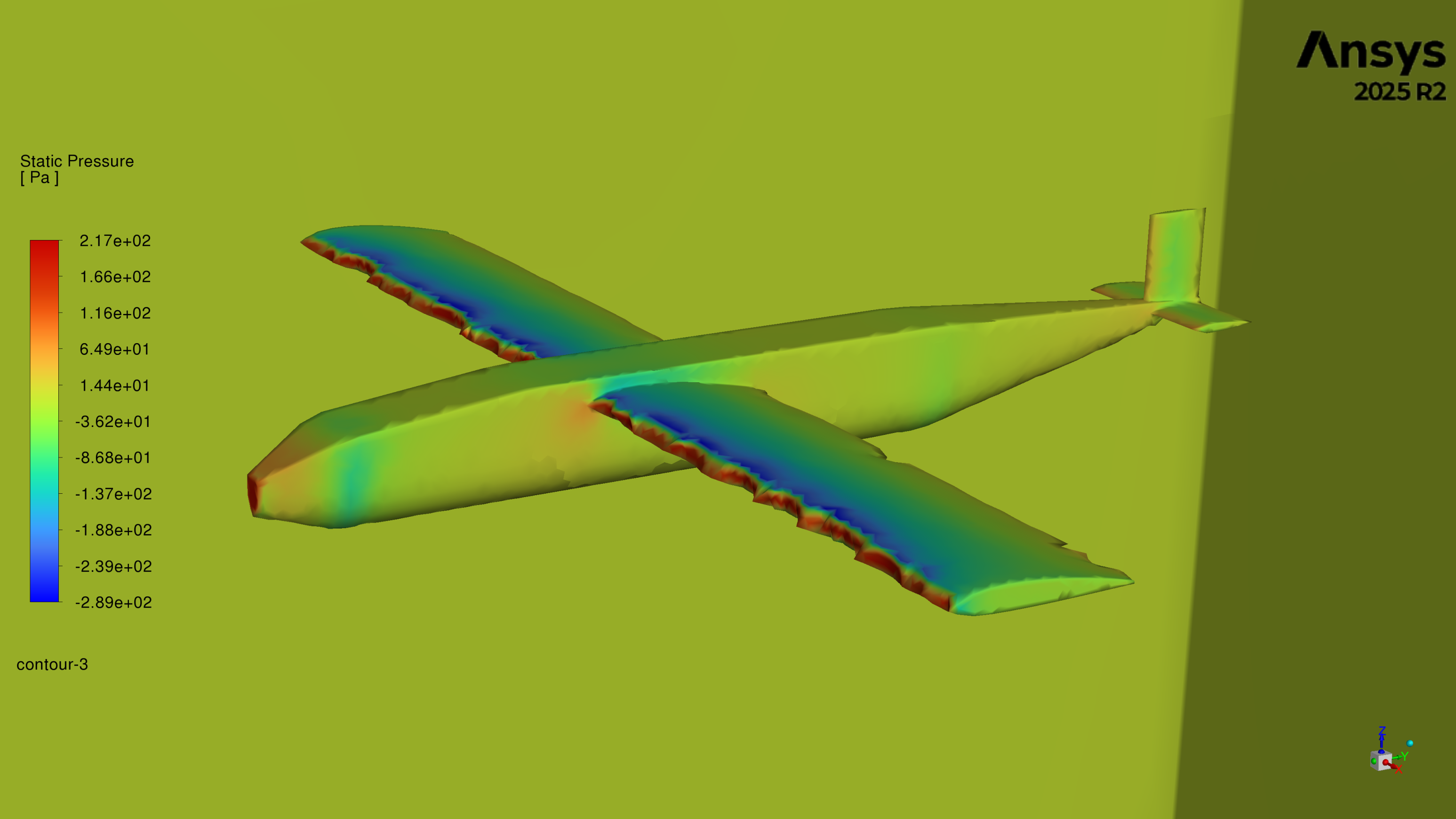
Pressure Distribution Analysis
Using ANSYS Fluent, we simulated the full aircraft at cruise conditions to visualize static pressure across every surface revealing the aerodynamic forces that generate lift and drag.
ANSYS
Fluent 2025 R2
Full 3D
Pressure Contour Mapping
Validated
Against Analytical Models
Aerodynamic Analysis
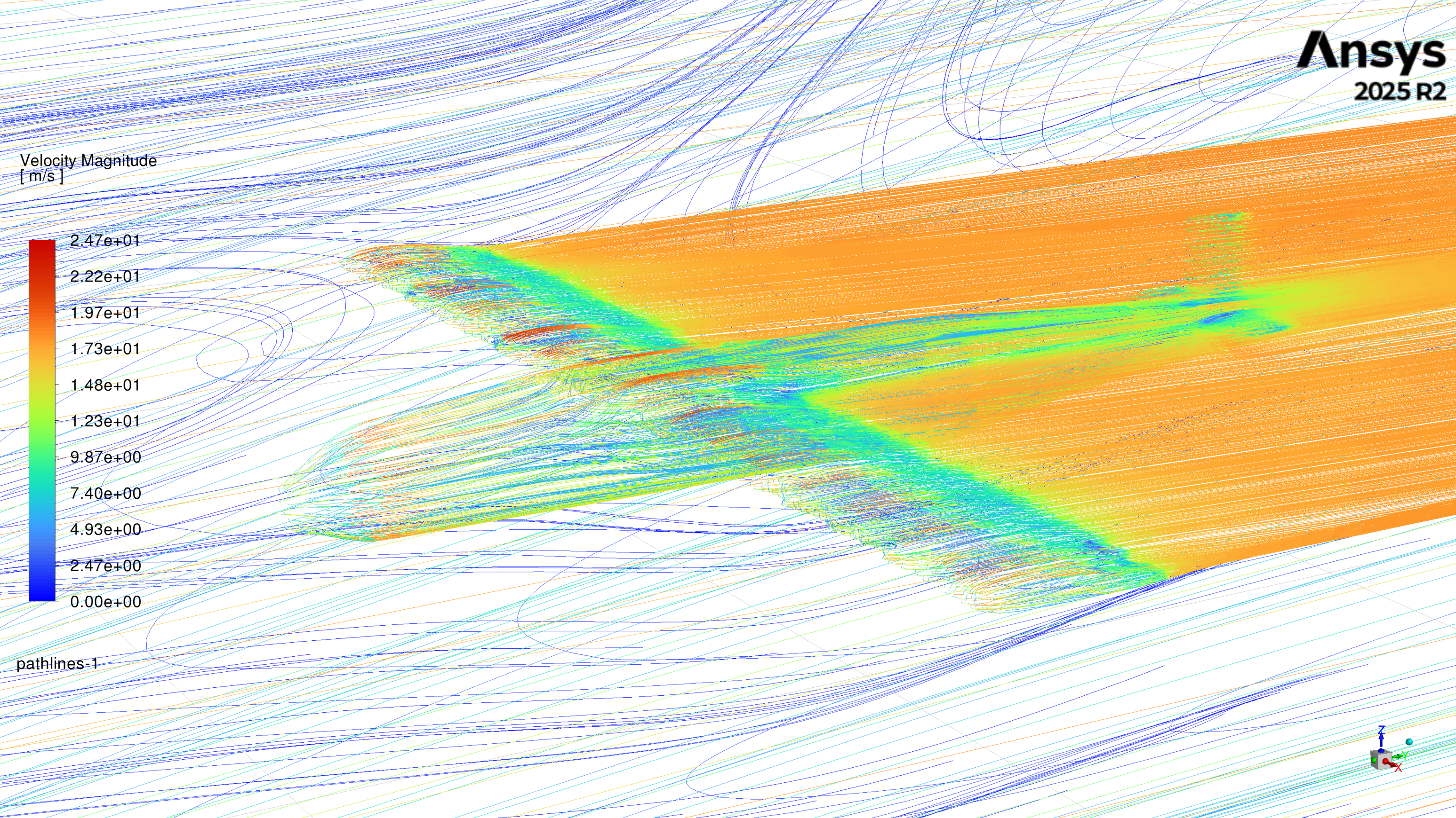
Velocity Pathlines
This velocity pathline visualization captures the complex airflow behavior around our aircraft. The color gradient from calm blue at the freestream to intense red in accelerated regions reveals how air interacts with every surface of the design.
These simulations help us identify regions of flow separation, turbulence, and recirculation, allowing us to refine the aircraft geometry for optimal aerodynamic performance before we ever build a physical prototype.
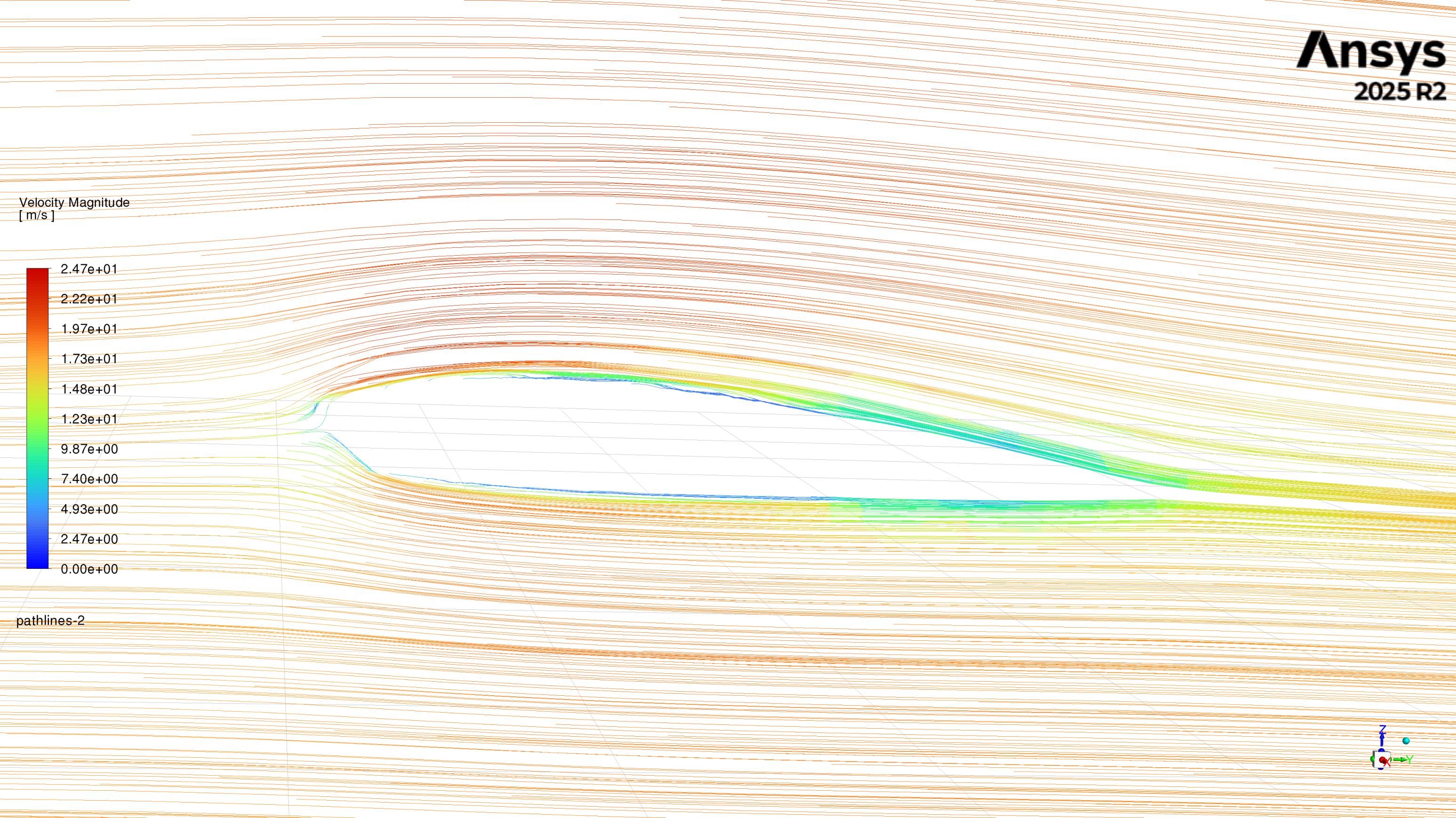
Airfoil Performance
Wing Cross-Section Flow
A closer look at the airflow around our selected airfoil. The velocity contour clearly shows accelerated flow over the upper surface creating the low-pressure region responsible for lift generation the fundamental principle driving our aircraft's performance.
The smooth, attached flow along both surfaces confirms our airfoil selection performs well at the design Reynolds number, with clean trailing-edge behavior indicating minimal parasitic drag.